How to Create a Production BOM for PCB Manufacturing?
08 February 2025
Views: 1010
A Bill of Materials (BOM) is a detailed list of all components, materials, and parts required to produce a PCB. Without a well-prepared BOM, the manufacturing process can face errors and failures.

Step 1: Understand the Purpose of a BOM
The BOM acts as a blueprint for the PCB assembly process. It can help identify: 1. Which components to use; 2. Where to place the components; 3. Component specifications.
Step 2: Gather key information for BOM
Before creating a BOM, you need to collect "
1. PCB design files: Export the design files from the PCB design software (e.g. Gerber, CAD files).
2. Component list: Identify all components used in the design, including their specifications and part numbers.
3. Manufacturer details: Research the manufacturer or supplier of each component.
Step 3: Build your BOM
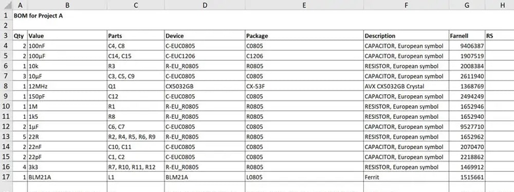
BOM documents are usually organized into a table format and contain the following columns:
1. Item/Line Number: A unique identifier for each component or material.
2. Reference Designator: A name used to locate a component on the PCB (e.g. R1, C3, U2).
3. Quantity: The quantity of each component required for one PCB assembly.
4. Component Description: A brief description of the component (e.g. 10kΩ resistor, 0.1µF capacitors).
5. Part Number: A unique code given to a component by the manufacturer or distributor.
6. Manufacturer Name: The name of the component manufacturer.
7. Package Type: The physical size and type of the component (e.g., SMD, DIP, QFN).
8. Package Dimensions: The PCB layout pattern of the component.
9. Alternate Part Number (optional): An alternate option in case the primary component is not available.
10 Comments: Additional information, such as special handling instructions or testing requirements.
Step 4: Generate BOM using PCB design software
The BOM creation process can be simplified using PCB design software such as Altium Designer, Eagle, or KiCAD. Steps: 1. Assign components in the schematic; 2. Verify PCB layout; 3. Export BOM.
Step 5: Verify and finalize BOM
After generating the BOM, double-check: 1. Component details; 2. Availability; 3. Cost; 4. Compliance.
Step 6: Share BOM with Manufacturer
After the BOM is finalized, share it with the PCB manufacturer. Provide the BOM along with the Gerber documentation, assembly drawings, and test requirements.
Conclusion
Creating a production BOM for PCB manufacturing is a meticulous process. By following the steps above, you can ensure that your BOM is accurate, detailed, and valid.


