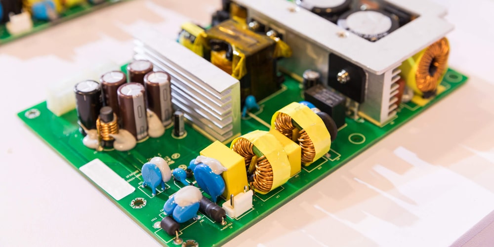
What is a Transformer PCB?
08 February 2025
Views: 1414
A Transformer PCB is a specialized PCB that integrates a transformer into a circuit. Transformers on PCBs are common in applications where voltage needs to be stepped up, stepped down, or signals need to be isolated, for transferring electrical energy between multiple circuits via electromagnetic induction.

Components of a Transformer PCB
1. Transformer Windings
A transformer on a PCB consists of windings made of multiple copper wires, separated by insulation layers to prevent electrical contact, and the windings are responsible for transferring energy between primary and secondary circuits via electromagnetic induction.
2. Core Material
The transformer core is made of laminated steel to concentrate the magnetic field generated by the windings. In PCB transformers, the core is sometimes integrated externally.
3. PCB Layers
A transformer PCB can have multiple layers to accommodate windings and connections, and a multi-layer design is often used to reduce size.
4. Thermal Management Features
Since the transformer generates heat during operation, the transformer PCB may include thermal vias, heat sinks, and other components to effectively dissipate the heat.
How Does a Transformer PCB Work?
The working principle of transformer PCB relies on electromagnetic induction, which occurs when AC flows through the primary winding. Then the primary winding, magnetic coupling, voltage conversion, and electrical isolation occur.
Application of transformer PCB
Transformer PCB is used in various industries due to its small size and high efficiency. Common applications include power supply, signal isolation, voltage regulation, industrial electronics, and medical equipment.
Conclusion
Transformer PCB is a compact and efficient solution for integrating transformers into electronic circuits. By utilizing electromagnetic induction, voltage conversion, signal isolation, and energy transmission can be achieved in various applications.
Share This Story, Choose Your Platform!


